Page 9 - Fireless
P. 9
ELESS PRODUCT GUIDE
5.2 Conventional panel mode using an auxiliary PSU
When used in this configuration, it is possible to combine a Fireless transponder and its associated wireless
field devices with an existing hard-wired conventional zone circuit, sounder circuit or a combination of both.
This enables Fireless field devices to seamlessly co-exist with existing fire detectors and sounders on the
same circuit.
The Fireless interface has been designed to be electrically compatible with most modern diode and non-
diode based conventional panels and field devices, whilst at the same time allowing wireless field devices to
share the fault monitoring capabilities of the conventional control panel. Faults reported by the wireless
interface are none-latching and it is not necessary to perform any local reset or silence operations following
the activation of an automatic detector or manual call point. Alarm and fault conditions transferred to the
conventional control panel by the wireless interface are collective; however, individual devices can still be
further diagnosed at the Fireless interface, which is fully addressable.
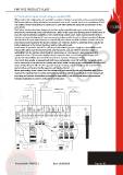
In this mode of operation, a local 17 to 28V dc ( 15mA minimum) power supply must be available at the
transponder, which must be battery backed, fault monitored, and can either be derived ( subject to
availability) from the existing conventional fire alarm panel, or a local power supply complying with
regulations in force. *If the power supply is local, it must also have a set of voltage free change-over
contacts (VFCO) available, and should be connected as shown in the diagram below.
The Fireless transponder is equipped with both Zone and Sounder circuit ‘IN’ and’ OUT’ terminals, which
can be connected at any point on the existing hard-wired radial circuit(s). In the configuration described and
shown below, Wi- Fyre will not take any power from the existing zone or sounder circuit and, therefore,
device loading and battery standby capacities will not be affected.
Before proceeding, please ensure that the existing zone and sounder circuits are compatible with Fireless
and that the required level of control and monitoring will be achieved. A specification for the transponder
zone/loop and sounder terminations is provided in Appendix F. A full test should always be performed
following installation in order to verify correct performance.
Document No.: PEN-FL2-2 Date: 29/06/2016 Page 9 / 30
5.2 Conventional panel mode using an auxiliary PSU
When used in this configuration, it is possible to combine a Fireless transponder and its associated wireless
field devices with an existing hard-wired conventional zone circuit, sounder circuit or a combination of both.
This enables Fireless field devices to seamlessly co-exist with existing fire detectors and sounders on the
same circuit.
The Fireless interface has been designed to be electrically compatible with most modern diode and non-
diode based conventional panels and field devices, whilst at the same time allowing wireless field devices to
share the fault monitoring capabilities of the conventional control panel. Faults reported by the wireless
interface are none-latching and it is not necessary to perform any local reset or silence operations following
the activation of an automatic detector or manual call point. Alarm and fault conditions transferred to the
conventional control panel by the wireless interface are collective; however, individual devices can still be
further diagnosed at the Fireless interface, which is fully addressable.
In this mode of operation, a local 17 to 28V dc ( 15mA minimum) power supply must be available at the
transponder, which must be battery backed, fault monitored, and can either be derived ( subject to
availability) from the existing conventional fire alarm panel, or a local power supply complying with
regulations in force. *If the power supply is local, it must also have a set of voltage free change-over
contacts (VFCO) available, and should be connected as shown in the diagram below.
The Fireless transponder is equipped with both Zone and Sounder circuit ‘IN’ and’ OUT’ terminals, which
can be connected at any point on the existing hard-wired radial circuit(s). In the configuration described and
shown below, Wi- Fyre will not take any power from the existing zone or sounder circuit and, therefore,
device loading and battery standby capacities will not be affected.
Before proceeding, please ensure that the existing zone and sounder circuits are compatible with Fireless
and that the required level of control and monitoring will be achieved. A specification for the transponder
zone/loop and sounder terminations is provided in Appendix F. A full test should always be performed
following installation in order to verify correct performance.
Document No.: PEN-FL2-2 Date: 29/06/2016 Page 9 / 30